
Push and drag are often taught as simple welding rules: push solid-wire MIG, drag stick and flux-cored wire. That shorthand can be useful, but it is not enough for a production drawing, a welding procedure, or a sheet-metal assembly where distortion and fit-up matter.
Travel direction changes where the arc acts on the weld pool, how easily the operator can see the joint, and how slag or shielding gas behaves around the puddle. It can also change bead profile and penetration. The right technique depends on the welding process, transfer mode, joint, welding position, material thickness, and the qualified welding procedure specification (WPS).
Define Push and Drag Before Discussing Technique
Push and drag describe the travel angle relative to the direction of travel—not whether the welder happens to move left or right.
- Push welding, also called forehand, means the electrode or gun points in the direction of travel.
- Drag welding, also called backhand, means the electrode or gun points back toward the completed weld.
The distinction matters because even a small change in travel angle can alter the arc’s interaction with the weld pool. It should not be confused with work angle, which positions the electrode relative to the joint faces.
Why Travel Direction Matters on Sheet-Metal Assemblies
Sheet-metal weldments are often more sensitive to heat input and bead shape than heavy plate fabrication. A bracket, enclosure, cabinet panel, or thin welded frame may need a controlled weld profile without excessive distortion, burn-through, cosmetic damage, or loss of fit.
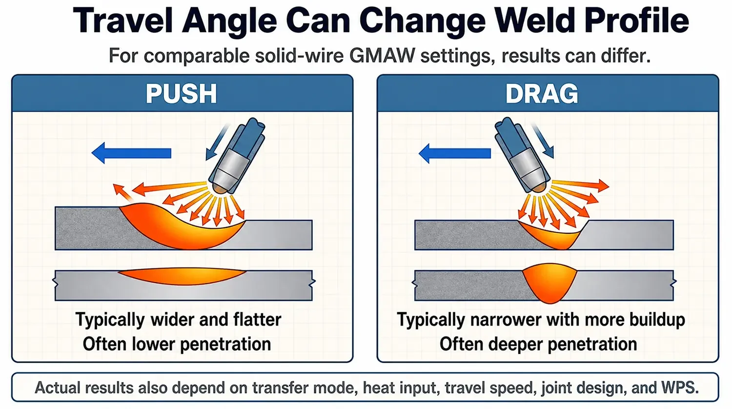
For a comparable setup, a push angle often produces a wider, flatter bead with less penetration. A drag angle often produces a narrower bead with more buildup and deeper penetration. This relationship is useful during process planning, but it does not replace a WPS: current, voltage, wire feed speed, stickout, travel speed, joint design, and position also affect the result.


SMAW: Slag Control Usually Favors a Drag Technique
Shielded metal arc welding (SMAW) produces slag from the electrode covering. In flat, horizontal, and overhead positions, a drag or backhand technique is commonly used to help keep slag behind the arc and away from the leading edge of the weld pool.
The practical lesson is not “stick welding always drags.” For vertical-up welding, the appropriate travel angle can be different. The welder’s job is to keep control of the leading edge of the puddle and prevent slag from running ahead of the arc. If slag becomes trapped in the weld, the result can include slag inclusions, poor fusion, and rework.

FCAW: Drag Is a Normal Starting Point, Not a Substitute for Procedure Control
Flux-cored arc welding (FCAW) also produces slag, so a drag technique is a normal starting point for many applications. Keeping the gun pointed back toward the weld pool can help prevent slag from moving ahead of the puddle.
However, position, wire classification, groove configuration, and the approved WPS still matter. Vertical welding and code-controlled work should follow the applicable procedure rather than a general rule of thumb.
GMAW: Push and Drag Are Both Process-Dependent Choices
Gas metal arc welding (GMAW) with solid wire is where oversimplified advice creates the most confusion.
For thin sheet metal, a push technique is commonly used because it can create a flatter bead and help the operator see the leading edge of the joint. Push technique is also common for pulsed and spray-transfer GMAW. With short-circuit transfer, either push or drag may be appropriate depending on the weld requirement and setup.
This distinction is especially relevant for custom sheet-metal fabrication:
- A thin panel may need a flatter, lower-penetration bead to reduce burn-through and post-weld finishing.
- A thicker bracket or structural feature may require more penetration, provided the joint design and WPS support that choice.
- A cosmetic seam may need different heat control and finishing allowances than an internal structural weld.
Travel angle is one control, not the entire process. The transfer mode, shielding gas, wire diameter, current, voltage, contact-tip-to-work distance, and travel speed all influence the final weld.


GTAW Should Be Set by the Joint and the Procedure
GTAW (TIG) gives the operator direct control over the torch, filler addition, and weld pool. The preferred torch orientation depends on joint access, welding position, base material, filler-metal handling, required bead shape, and the approved procedure.
For that reason, a general article should not prescribe one universal TIG travel direction or angle. If GTAW is used on a visible enclosure corner, thin stainless assembly, or aluminum component, the production team should establish the torch angle, travel speed, filler addition method, and heat-control approach through the applicable procedure and qualification work.
A Practical Comparison for Drawing Review and Production Planning
| Process | Useful Starting Approach | Why It Is Commonly Used | What Can Change the Choice |
|---|---|---|---|
| SMAW | Drag in many flat, horizontal, and overhead applications | Helps manage slag behind the arc | Vertical-up technique, electrode type, joint, WPS |
| FCAW | Drag is commonly used | Helps prevent slag from moving ahead of the puddle | Position, wire classification, procedure requirements |
| Solid-wire GMAW | Push is common for thin sheet, spray, and pulsed work; short-circuit may use either | Can improve joint visibility and create a flatter bead | Transfer mode, thickness, penetration requirement, joint access |
| GTAW | Establish through procedure and joint requirements | Torch and filler control are highly application-specific | Material, position, joint, filler access, cosmetic requirement |
This table is a planning aid, not a substitute for a WPS or welder qualification requirement.

What to Check Before Releasing a Welded Sheet-Metal Design
Travel direction is an operator-level choice, but design and production teams can reduce welding risk before the first part is made.
- Identify whether the weld is structural, sealing, cosmetic, grounding-related, or primarily for assembly retention.
- Specify the required weld size, length, location, and acceptance criteria clearly on the drawing.
- Check access for the torch, gun, clamps, fixtures, and inspection tools.
- Consider whether a continuous weld is necessary or whether an intermittent weld can reduce distortion.
- Confirm that heat input and weld sequence will not pull critical features out of tolerance.
- Reserve enough space for grinding, finishing, coating, or hardware installation where those operations follow welding.
- Use a qualified WPS whenever code, customer, or internal quality requirements call for one.
For enclosure and cabinet work, one detail worth checking during drawing review is whether a weld will sit near a door opening, gasket surface, mounting interface, or cosmetic exterior panel. A technically sound weld can still create a production problem if distortion prevents a panel from seating or if finishing cannot restore the required appearance.
The Useful Rule Is Not “Always Push” or “Always Drag”
Slag-producing processes often start with a drag technique because the welder needs to keep slag from interfering with the leading edge of the puddle. Solid-wire GMAW often uses a push technique for thin material and certain transfer modes because bead shape, visibility, and heat control can be advantageous.
But those are starting points. The final direction must suit the process, transfer mode, material, joint, position, required penetration, and WPS. Treating push and drag as fixed slogans can create avoidable quality problems; treating them as controlled variables leads to more reliable sheet-metal weldments.

