

Cooling problems rarely begin with the sheet metal, but the rack is where the consequences show up. A manifold can fit in CAD and still block a power whip, overload a rear door, or leave no hand space to uncouple a server.
That is why an AI server rack should not be chosen from an air‑versus‑liquid label alone. Start with how the IT equipment rejects heat, what the facility can support, and which mechanical interfaces the enclosure has to carry. The cabinet geometry follows from those answers.
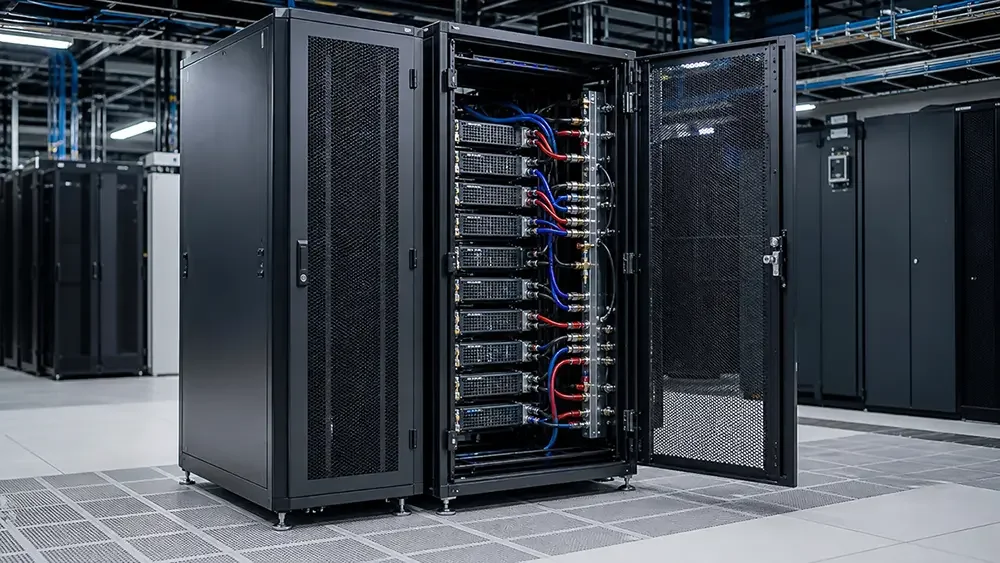
Air and liquid interfaces have to share one serviceable rack envelope
|
Three terms to settle before comparing racks •PUE belongs to the data center, not the cabinet. Cooling architecture can affect facility energy use, but a rack does not come with a fixed PUE value. •“Full liquid cooling” is too vague for a drawing. Direct-to-chip cold plates, rear-door heat exchangers, and immersion tanks create different structures and service procedures. •There is no universal rack-kW cutoff. The workable boundary depends on the server, airflow, climate, containment, liquid temperatures, redundancy, and operating plan. |
1.Separate the Cooling Architectures Before Comparing Them
The original three‑way comparison—air, cold plate, and “all liquid”—is a useful starting idea, but the last category needs to be unpacked.
Air‑cooled racks
An air‑cooled rack uses the server fans and the room air system to move heat from the IT equipment to the facility cooling plant. For the sheet‑metal design, the important questions are front‑to‑rear pressure drop, bypass control, blanking, cable congestion, and whether the doors and containment interfaces match the tested airflow direction.
Door open area is only a geometry input. Two doors quoted at 70% open area can have different resistance because of hole pattern, stiffeners, filters, hinges, and a second inner skin. Ask for pressure drop at the expected rack airflow, then confirm inlet temperature with the final server and cable population.
Direct‑to‑chip cold‑plate racks
Direct‑to‑chip, or D2C, cooling brings a technology cooling system to cold plates on the CPU, GPU, or other named components. A supply‑and‑return manifold distributes fluid to each server. The server vendor should state the liquid heat‑capture fraction and the remaining air load; “liquid cooled” does not mean the rack can automatically give up fans or perforated doors.
For deeper manufacturing‑focused details on manifold and cabinet construction for this architecture, read our companion article: Liquid‑Cooled AI Rack Enclosures: Critical Sheet‑Metal Design Considerations.
Rear‑door heat exchanger racks
A rear‑door heat exchanger transfers server exhaust heat to a liquid loop at the back of the cabinet. It may be passive or fan‑assisted. Mechanically, this is a door‑weight and service problem as much as a thermal one: filled mass, hinge moment, hose motion, door swing, rear depth, condensate risk, and removal procedure all belong on the rack interface drawing.
Immersion systems
Immersion cooling places IT hardware in a dielectric‑fluid tank. That can be a valid architecture, but it is not a conventional 19‑inch cabinet with extra plumbing. The enclosure must be treated as a tank system, with its own fluid compatibility, lifting, sealing, fire, service, and floor‑load requirements.
|
Architecture |
Heat-transfer boundary |
Residual air path |
Primary enclosure impact |
|
Air cooled |
Server to room air |
Carries the IT heat load |
Perforated doors, sealing, cable control, containment |
|
D2C cold plate |
Selected components to a TCS loop |
Usually remains for uncooled components |
Manifold, QDs, hoses, drip path, mixed air/liquid service |
|
Rear-door HX |
Server exhaust air to liquid at the door |
Air still moves through the server |
Door structure, hinges, hoses, rear clearance, condensation control |
|
Immersion |
IT hardware directly to dielectric fluid |
Not a conventional rack air path |
Tank, lid, lifting, service fixtures, fluid and fire strategy |
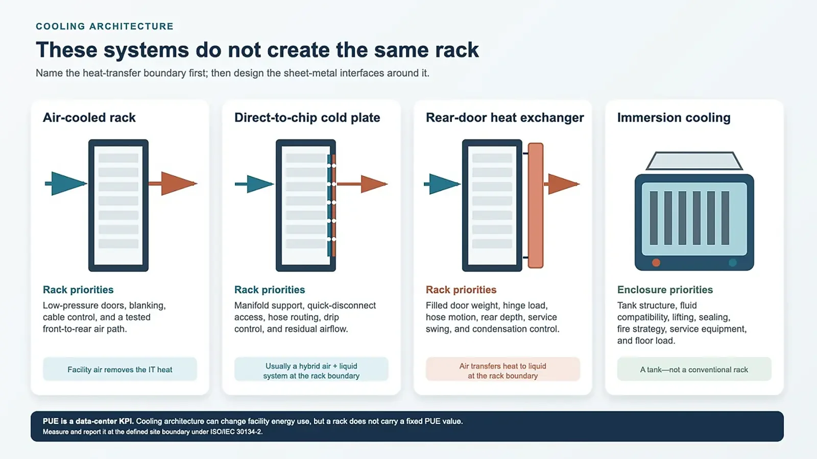
Name the heat-transfer boundary before comparing rack designs
2.Turn the Cooling Loop Into Rack Interfaces
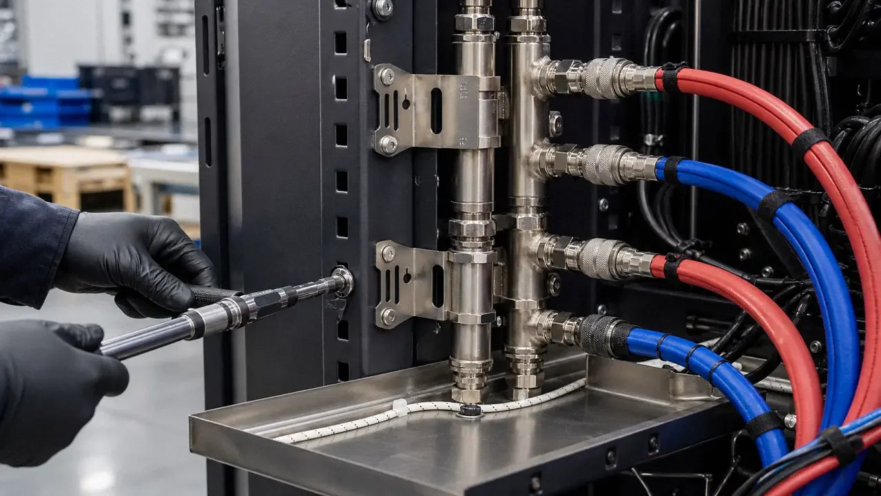
On a liquid‑cooled rack, the manifold is not a late‑stage accessory. It carries filled weight, connection forces, shipping vibration, and repeated service loads. The rack also has to keep hoses and quick disconnects clear of power distribution, network cabling, rail latches, and the rear door.
Support the manifold without trapping the service team
OCP manifold guidance recommends a rack mounting plate or bracket and calls out serviceability, flow control, and suitable quick disconnects. In practice, the bracket needs a defined datum, local stiffness, and enough adjustment to absorb build tolerance without letting the manifold wander into the server removal path.
A common pitfall we see is giving the PDU, vertical cable manager, and manifold the same rear corner. Each item fits by itself; the assembled rack does not. Put the mating hand path, hose sweep, torque‑tool access, and isolation‑valve reach into the CAD model before the rear rails are released.
Control hoses, drips, and mixed‑metal contact
Use the hose supplier’s minimum bend radius and the quick‑disconnect supplier’s mating envelope. Provide edge protection where a hose can touch sheet metal, and restrain the hose without pinching it. A shallow stainless drip tray and leak‑detection cable can make a small release visible, but the tray should not hide fittings or create a basin that cannot be inspected or drained.
Fluid compatibility belongs to the entire wetted‑material list—manifold, seals, QDs, hoses, valves, and coolant—not just the rack bracket. Where stainless, aluminum, zinc‑coated sheet, and painted carbon steel meet, review galvanic contact, drainage, coating damage, and the intended bonding path.
Keep the air side in the design
D2C systems often retain an air path for power supplies, memory, storage, and networking. ASHRAE recommends looking at the air and liquid networks together. The rack specification should therefore include both the expected air‑flow/pressure‑drop condition and the liquid flow, pressure, temperature, water class, and redundancy boundary supplied by the server and cooling‑system teams.
|
Information worth freezing before the rack drawing •Manifold: location, supply/return orientation, mounting datum, filled mass, isolation, removal direction, and connection forces. •Quick disconnects: hand-mate or blind-mate type, keying, drip performance, mating envelope, tool access, and replacement procedure. •Hoses and cables: bend radius, abrasion control, restraint, hot-swap path, PDU position, cable volume, and door interference. •Temperature boundary: server-declared liquid class, CDU approach temperature, site dew point, insulation, sensors, and shutdown response. •Responsibility split: which supplier owns the frame, manifold, QDs, loop pressure test, flushing, water chemistry, and commissioning. |
3.Size the Cabinet From the Installed Equipment
A rack envelope should be the result of a dimensional stack‑up, not the first input. Start with the chassis, rail kit, connectors, cable‑management arm, PDU, manifold, QDs, hose bend, door structure, and the space a technician needs to service them.
From reviewing hundreds of AI‑rack RFQs, we frequently see teams lock in fixed outer cabinet dimensions too early, before mapping manifold routing, cable bundles and required technician service clearance.
Do not mix 19‑inch and OCP rack ecosystems
IEC 60297 defines the 482.6 mm (19‑inch) series, and one rack unit is 44.45 mm (1.750 in.) high. OCP Open Rack uses a 21‑inch equipment bay and a 48 mm OpenU. Some Open Rack V3 configurations can support 19‑inch equipment with the specified interface, but that does not make the mounting systems interchangeable. Name the base‑frame specification, rails or adapters, power interface, and manifold standard on the drawing.
Use common cabinet sizes as starting envelopes
For 19‑inch enterprise racks, discussions often begin around 42–48U, 600 or 800 mm (23.6 or 31.5 in.) wide, and 1,000 or 1,200 mm (39.4 or 47.2 in.) deep. An 800 × 1,200 mm cabinet is often easier to integrate when vertical PDUs and a side or rear manifold have to coexist. It is still only a starting point. The actual rail‑adjustment range, server depth, connector bodies, cable bend radius, quick‑disconnect access, and door swing decide whether it works.
In our experience, the rear service zone disappears a few millimeters at a time: a deeper plug body, a wider hose sweep, an added sensor bracket, then a stiffener inside the door. A full‑scale fit check with the real rail kit and representative hoses is inexpensive compared with moving rails after coating.
Define the load case, not just the load rating
A full‑height AI rack may enter design discussions with a static payload in the 1,200–2,000 kg (2,646–4,409 lb) range. Treat that as a scoping range, not a catalog promise. The released payload map, center of gravity, partial‑population cases, liquid‑filled hardware, rear‑door moment, caster or leveling‑foot position, anchorage, floor rating, and shipping condition determine the structure.
A 1,500 kg rack with dense GPU trays high in the cabinet is not the same structure as a uniformly loaded 1,500 kg rack. Ask the test plan to reproduce the critical configuration and record deflection at named points, door and latch operation under load, and residual set after unloading.
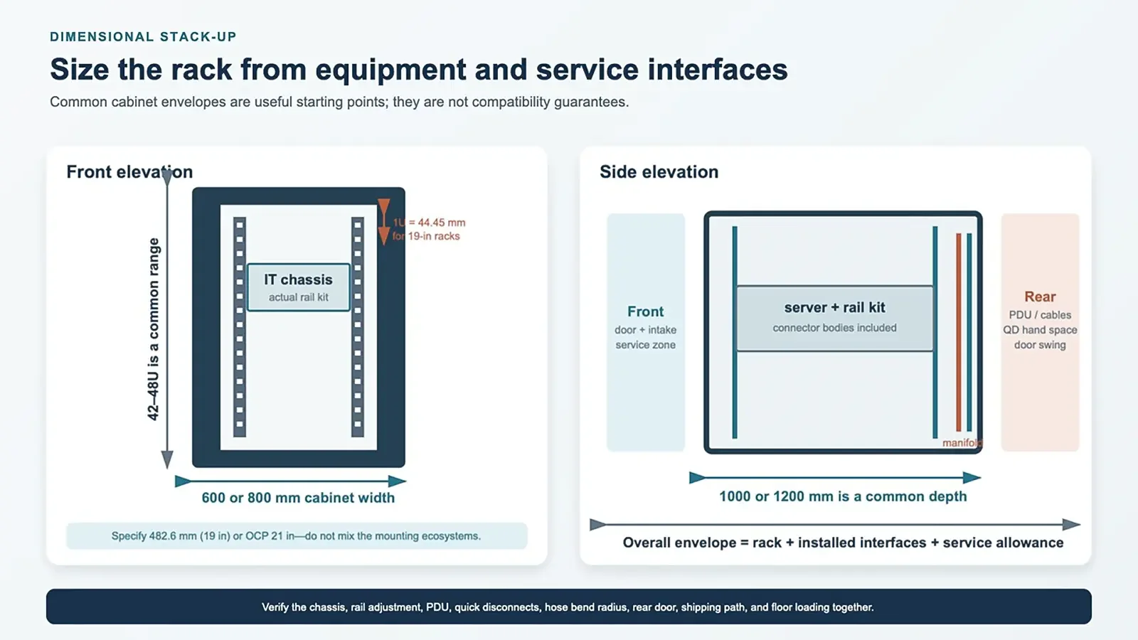
Build the cabinet around the installed equipment and service stack-up
4.Choose Materials and Fabrication Details as a System
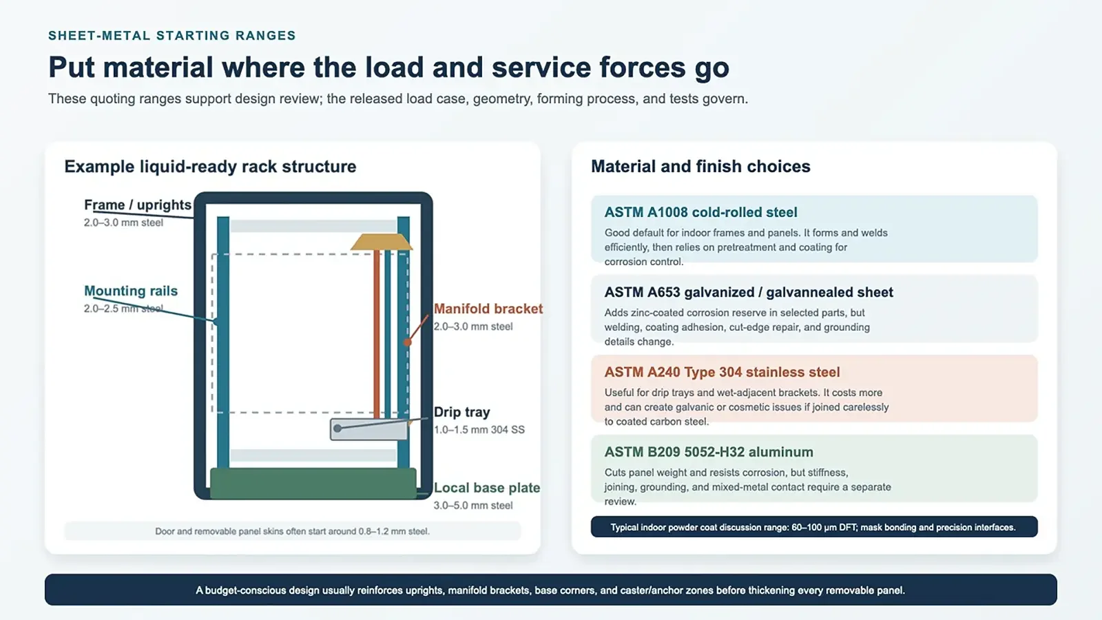
For a dry indoor data hall, ASTM A1008 cold‑rolled steel is a practical baseline for frames, rails, doors, and panels. ASTM A653 galvanized or galvannealed sheet can add corrosion reserve in selected parts, while Type 304 stainless steel is useful for drip trays and wet‑adjacent brackets. ASTM B209 5052‑H32 aluminum can reduce panel weight, but stiffness, joining, bonding, and mixed‑metal contact need their own review.
We apply similar material‑first‑principles when building custom energy‑storage sheet‑metal enclosures, prioritizing load paths and wet‑zone separation over full‑material upgrades.
The ranges below are typical design‑review starting points for fabricated racks. They are not standard‑mandated thicknesses; section shape, material grade, payload, joint spacing, and test results can move them.
|
Component |
Starting material |
Typical thickness |
What drives the final choice |
|
Frame uprights and crossmembers |
A1008 steel |
2.0–3.0 mm |
Section depth, torsion, payload map, weld or bolt joints |
|
Mounting rails |
A1008 or coated steel |
2.0–2.5 mm |
Cage-nut fit, hole quality, rail reaction, full-height alignment |
|
Doors and removable panels |
A1008 or A653 sheet |
0.8–1.2 mm |
Perforation, hems/returns, handling, oil-canning, finish |
|
Manifold brackets |
Coated steel or 304 SS |
2.0–3.0 mm |
Filled mass, connection force, vibration, adjustability |
|
Base and local reinforcement |
A1008 steel |
3.0–5.0 mm local |
Caster/foot reactions, anchors, transport and tip cases |
|
Drip tray |
304 stainless steel |
1.0–1.5 mm |
Drainage, cleaning, sensor support, formed-edge stiffness |
Budget tradeoff: reinforce the load path first
When the material budget is tight, making every panel thicker usually adds cost and shipping weight without fixing the critical load path. A more useful approach is to reinforce uprights, rail brackets, manifold mounts, base corners, and caster or anchor zones, then use formed returns and hems to stiffen removable panels.
The same logic applies to corrosion. In a controlled indoor room, an all‑stainless rack is rarely necessary. A powder‑coated carbon‑steel frame with stainless wet‑adjacent parts can be a reasonable split. The tradeoff is more attention to isolation, bonding, coating damage, and drainage at the mixed‑material joints.
Release the bends, joints, and finish together
An inside bend radius around 1.0–1.5 times material thickness is a sensible starting discussion for many cold‑rolled sheet parts, but the alloy, temper, grain direction, tooling, and cosmetic face still govern. Keep holes, slots, and self‑clinching hardware far enough from bends to meet the fastener and tooling supplier’s limits. On long uprights, fixture datums and weld sequence usually matter more than adding another decimal place to the flat‑pattern tolerance.
For indoor powder coating, 60–100 μm (2.4–3.9 mil) dry‑film thickness is a common project range. Specify the pretreatment, color and texture, cure, masked bonding points, threaded features, rail fits, and cosmetic zones. ASTM D3359 can classify tape‑test adhesion, while ASTM D7091 covers nondestructive dry‑film‑thickness measurement. The drawing should state the required method and acceptance level rather than simply saying “good adhesion.”
Starting thickness ranges should follow the load path and wet-adjacent zones
5.Verify the Rack Before It Ships
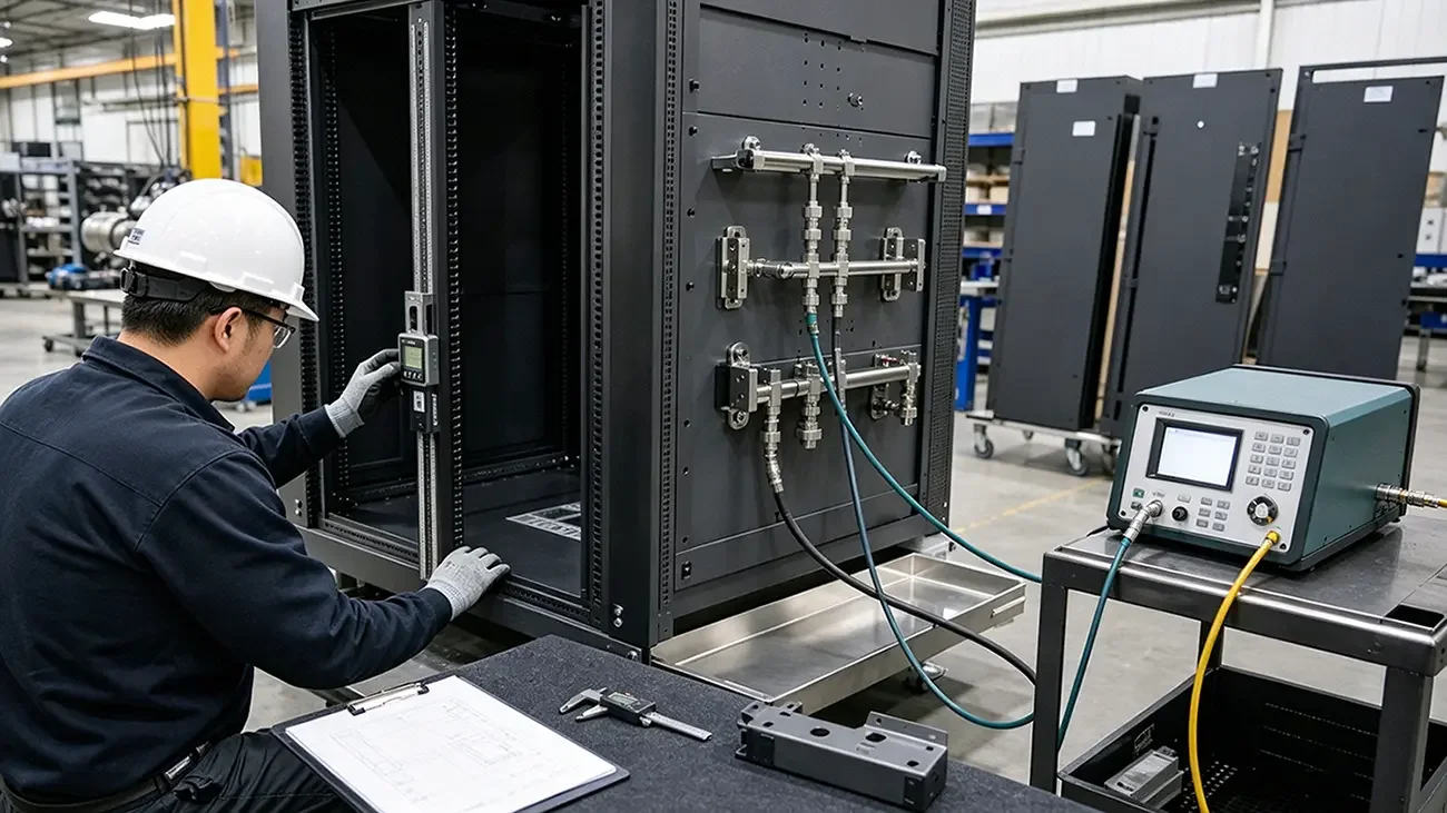
The inspection plan should separate enclosure geometry from coolant‑loop integrity. A square frame does not prove a leak‑tight manifold, and a passed pressure test does not prove that the server rails align or the rear door clears the hoses.
Use measurable dimensional and functional checks
The numbers below are reasonable starting targets for a custom full‑height rack. They are examples, not universal requirements. The released drawing and test procedure should define the datum, support condition, measurement method, temperature, and pass/fail rule.
|
Check |
Example starting target |
Context that must be stated |
|
Frame squareness |
Diagonal difference ≤ 3 mm |
Reference faces, support points, doors/panels installed or removed |
|
Mounting-rail plane |
Coplanarity within 1 mm |
Defined datum, top/middle/bottom points, rail fastener torque |
|
Formed feature |
±0.5 mm where practical |
Material, bend count, dimension origin, functional criticality |
|
Load hold |
Released payload map; ≥1 h if specified |
Payload distribution, proof factor, supports, temperature, deflection points |
|
Post-load function |
No door, latch, panel, or rail-kit binding |
Check under load and after unload; record residual set |
|
Powder coat |
60–100 μm DFT if specified |
Coating system, measurement method, sample locations, masked zones |
Qualify the manifold and quick disconnects to their own boundary
A production leak check may use pressure decay, vacuum decay, tracer gas, or another agreed method. The pressure, test medium, stabilization time, hold time, allowable decay, temperature compensation, and safety controls must come from the manifold and quick‑disconnect qualification—not from a generic rack checklist. A proof pressure such as 1.25–1.5 times operating pressure is sometimes used in engineering programs, but it should never be applied blindly across seals, QDs, sensors, or assembled servers.
Also record wetted materials, cleanliness or flushing status, connection torque where applicable, sensor continuity, valve position, and protective caps for shipping. If the rack factory installs only brackets and a drip tray, say so. The final inspection record should not imply that an uninstalled or separately supplied loop has been qualified.
Call out certification only when the project needs it
UL 2416 covers cabinet, enclosure, and rack systems used with information and communication technology equipment. Immersion enclosures have a separate UL 2416A path. Certification scope, authority‑having‑jurisdiction requirements, seismic qualification, and any NEMA or IEC ingress rating should be agreed before fabrication. A highly perforated indoor server rack is not automatically a rated environmental enclosure.
|
A concise shipment record •Mechanical: dimensional report, rail fit check, payload configuration, load/handling results, door and panel function. •Cooling hardware: manifold/QD part revision, pressure or leak-test record, sensor check, valve state, cleanliness and shipping protection. •Finish and bonding: DFT readings, adhesion result if required, masked points, continuity test method and result where specified. •Configuration: controlled photos showing PDUs, manifolds, hoses, cable managers, trays, sensors, doors, labels, and accessories as shipped. |
6.Use the Actual Project to Choose the Cooling Path
The useful choice is not “old air cooling” versus “advanced liquid cooling.” It is the architecture that fits the server platform, facility, maintenance team, risk tolerance, and budget without creating an unserviceable rack.
Scenario 1: retrofit an existing enterprise data hall
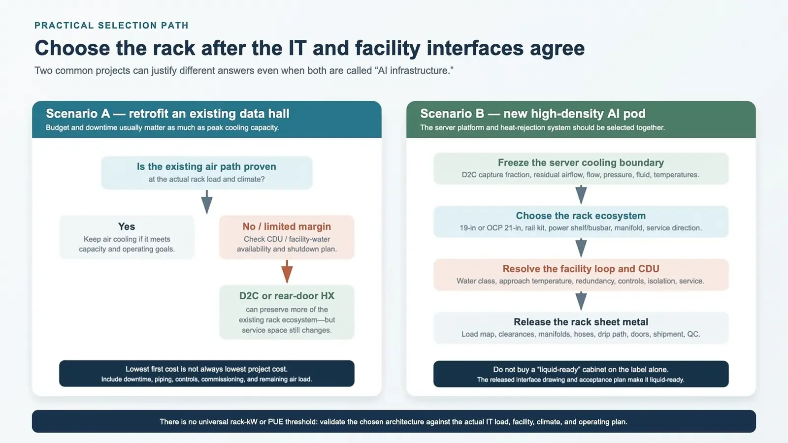
If the current air path has measured capacity at the target load, keeping an air‑cooled rack may be the lowest‑risk answer. Spend the budget on containment gaps, door pressure drop, cable congestion, blanking, and commissioning before replacing the enclosure.
If a limited group of CPU or GPU nodes is the constraint and the site can support a CDU or facility‑water connection, D2C cold plates can preserve much of the existing rack ecosystem. A rear‑door heat exchanger may also suit a retrofit when room heat rejection is the main issue. Neither option is “drop‑in” until the rear service zone, hose route, downtime, controls, water quality, residual air load, and commissioning plan are confirmed.
Scenario 2: build a new high‑density AI pod
For a new pod, select the server cooling boundary and facility heat‑rejection path together. Freeze the D2C capture fraction, residual airflow, coolant, supply temperature class, flow, pressure drop, CDU arrangement, and redundancy. Then select the 19‑inch or OCP rack ecosystem and release the manifold, power, cable, structural, and service interfaces as one package.
Immersion may make sense for a platform designed around tank service, but rack density alone does not make it the default. D2C and rear‑door systems often offer a more familiar service model, while immersion changes hardware handling, fluid management, lifting, fire strategy, and floor layout. Compare the operational model as carefully as the thermal capacity.
Retrofits and new AI pods follow different cooling decision paths
7.Use the Rack Specification as the Decision Record
An AI server rack is ready for fabrication when the cooling boundary, equipment interface, load map, service envelope, materials, and acceptance tests agree. Air cooling can remain sensible where the measured airflow has margin. D2C and rear‑door systems can support denser loads, but they add liquid and service interfaces that the sheet metal has to carry without blocking the people who maintain the rack.
The final choice should leave a clear technical record: what heat stays in the air, what moves to liquid, where each interface sits, which supplier owns it, and how the assembled rack will be verified. That record is more useful for material and process selection than a generic claim about the “best” cooling technology.
Key Takeaways
- Do not select rack outer dimensions first. Define your cooling heat‑transfer boundary before finalizing cabinet geometry.
- Air‑cooled, D2C cold‑plate, rear‑door heat‑exchanger and immersion systems create fundamentally different sheet‑metal requirements.
- Even liquid‑cooled racks often retain residual air‑cooling paths for uncooled server components.
- Define payload map, center‑of‑gravity and service clearance, do not rely purely on catalog static payload numbers.
- Optimize material selection by reinforcing critical load‑path zones; full‑stainless construction is rarely required for indoor data‑hall racks.
- Separate dimensional geometry inspection from manifold and coolant‑loop leak‑test acceptance criteria.
- Document supplier ownership for every mechanical, cooling and facility interface to reduce costly late‑project changes.
If you are preparing RFQ or drawing specifications for air‑or liquid‑cooled AI server racks, our engineering team can review your sheet‑metal requirements for common fabrication pitfalls.